


Pin Numbering - Raspberry Pi 400
Numbering Scheme
Pi4J (by default) uses an abstract pin numbering scheme to help insulate software from hardware changes.
Pi4J implements the same pin number scheme as the Wiring Pi project. More information about the WiringPi pin number scheme can be found here: http://wiringpi.com/pins/
Pi4J provides a RaspiPin enumeration that is used to manage the accessible GPIO pins.
(NOTE: Pi4J also can be configured to use the Broadcom Pin numbering scheme.)
Please see this page for more information on both the WiringPi and Broadcom pin numbering schemes:
>> Pin Numbering Schemes
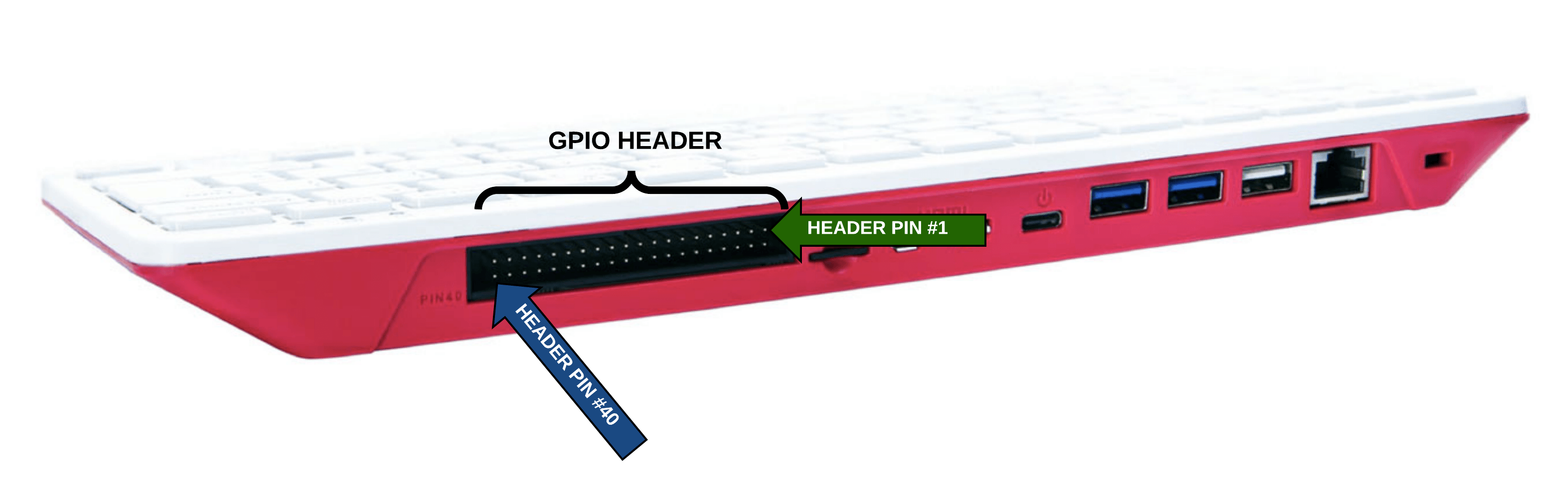
Expansion Header
The Raspberry Pi 400 contains a single 40-pin expansion header located on the back of the keyboard housing providing access to 28 unique GPIO pins.

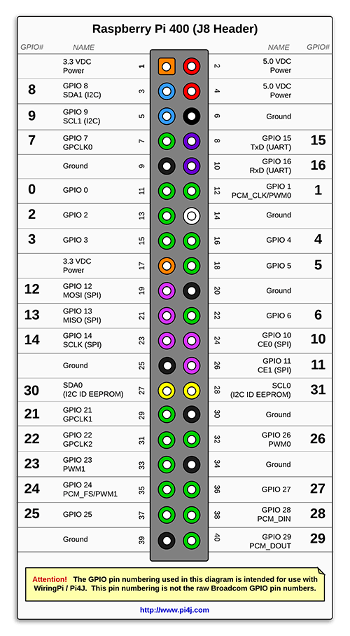
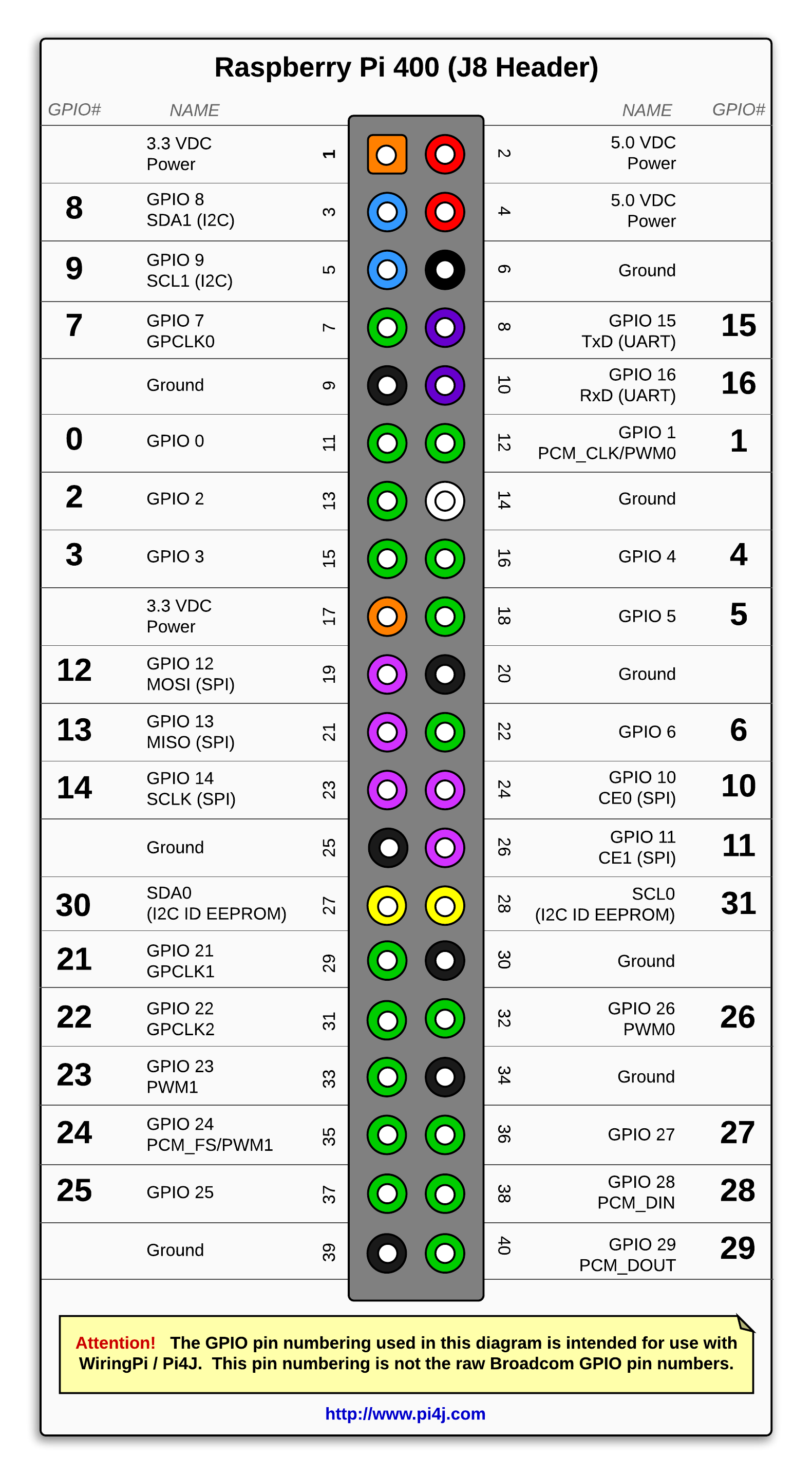
GPIO Pinout (40-pin Header)
The diagram below illustrates the GPIO pinout using the Pi4J/WiringPi GPIO numbering scheme.
Known Issues
On Raspberry Pi models starting with model 3B (including Raspberry Pi Model 400) the hardware-based serial/UART device /dev/ttyAMA0 has been re-purposed to communicate with the the built-in Bluetooth modem and is no longer mapped to the serial RX/TX pins on the GPIO header. Instead, a new serial port "/dev/ttyS0" has been provided which is implemented with a software-based UART (miniUART). This software-based UART ("/dev/ttyS0") does not support PARITY and some have experienced some stability issues using this port at higher speeds. If you don't need Bluetooth functionality, you can disable the BT modem and configure the RPi to use a device-tree overlay to re-map the hardware-based serial UART ("/dev/ttyAMA0") back to the GPIO header pins for TX/RX. See the instructions on this page for details on how to configure the device-tree overlay and disable the bluetooth modem/service:
Disable Bluetooth Modem
Additional Resources
- Please visit the usage page for additional details on how to control these pins using Pi4J.
- Click here for more information on the Raspberry Pi Model 400.
- Click here for more information the Raspberry Pi pin functions.