


Pin Numbering - Odroid XU4
- Platform Configuration
- Numbering Scheme
- Expansion Headers
- XU4 Shifter Shield
- CON10 Pinout (30-pin Header)
- CON11 Pinout (12-pin Header)
- XU4 Shifter Shield Pinout (40-pin Header)
- Examples
- Known Issues
- Additional Resources
Platform Configuration
Unlike the RaspberryPi, to use the BananaPi board you must first configure the Pi4J library to use an alternate platform implementation.
There are three methods to configure the platform. You are free to use any of these three methods.
- Method 1 : Environment Variable
You can set the "PI4J_PLATFORM" environment variable to a value of "odroid".
- Method 2 : Java System Property
You can configure a Java system property named "pi4j.platform" to a value of "odroid".
- Method 3 : Inline Java Code
You can configure the platform in your Java code before you instantiate the Pi4J controller instance.
// ####################################################################
//
// since we are not using the default Raspberry Pi platform, we should
// explicitly assign the platform as the Odroid platform.
//
// ####################################################################
PlatformManager.setPlatform(Platform.ODROID);
Numbering Scheme
Pi4J uses an abstract pin numbering scheme to help insulate software from hardware changes.
Pi4J implements the same pin number scheme as the Wiring Pi project. More information about the WiringPi pin number scheme can be found here: http://wiringpi.com/pins/
Pi4J provides a OdroidXU4Pin enumeration that is used to manage the accessible GPIO pins.
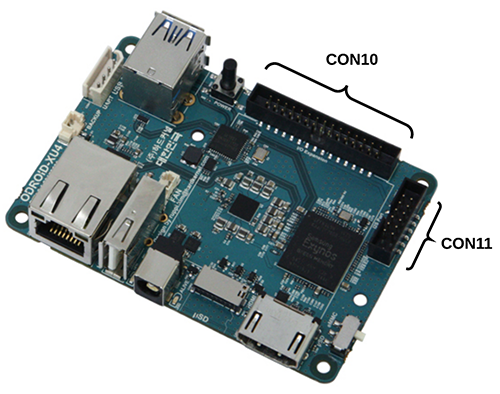
Expansion Headers
The Odroid XU4 board contains a 30-pin GPIO expansion header labeled CON10 providing access to 22 GPIO pins and 2 AIN (analog input) pins. The Odroid XU4 board also includes a 12-pin header labeled CON11 which provides an additional 2 GPIO pins.\
WARNING: All GPIO and AIN pins use 1.8VDC for signaling. Do not attempt to connect 3.3VDC or 5VDC to these header pins.
(The CON10 and CON11 headers are illustrated below)
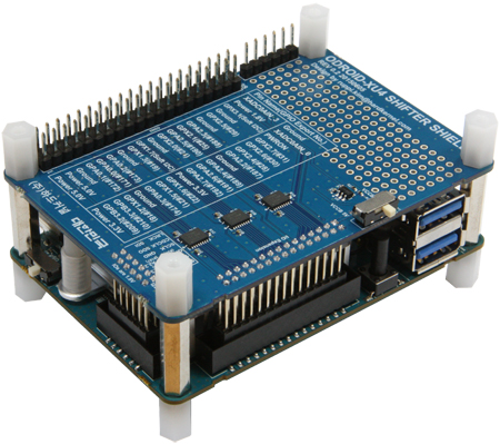
XU4 Shifter Shield
The Odroid XU4 board has an optional accessory XU4 Shifter Shield board that re-aligns the pins to closely match the pinout on a Raspberry Pi 40-pin GPIO header. The shifter shield also level shifts the voltages on the GPIO pins to use either a 3.3VDC or 5.0VDC reference rather than the 1.8VDC reference voltage on the XU4 board.
If you are a hobbyist and/or comfortable using Arduino and Raspberry Pi, then this shifter shield is highly recommended.
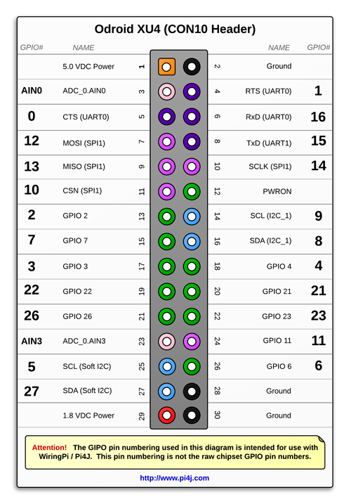
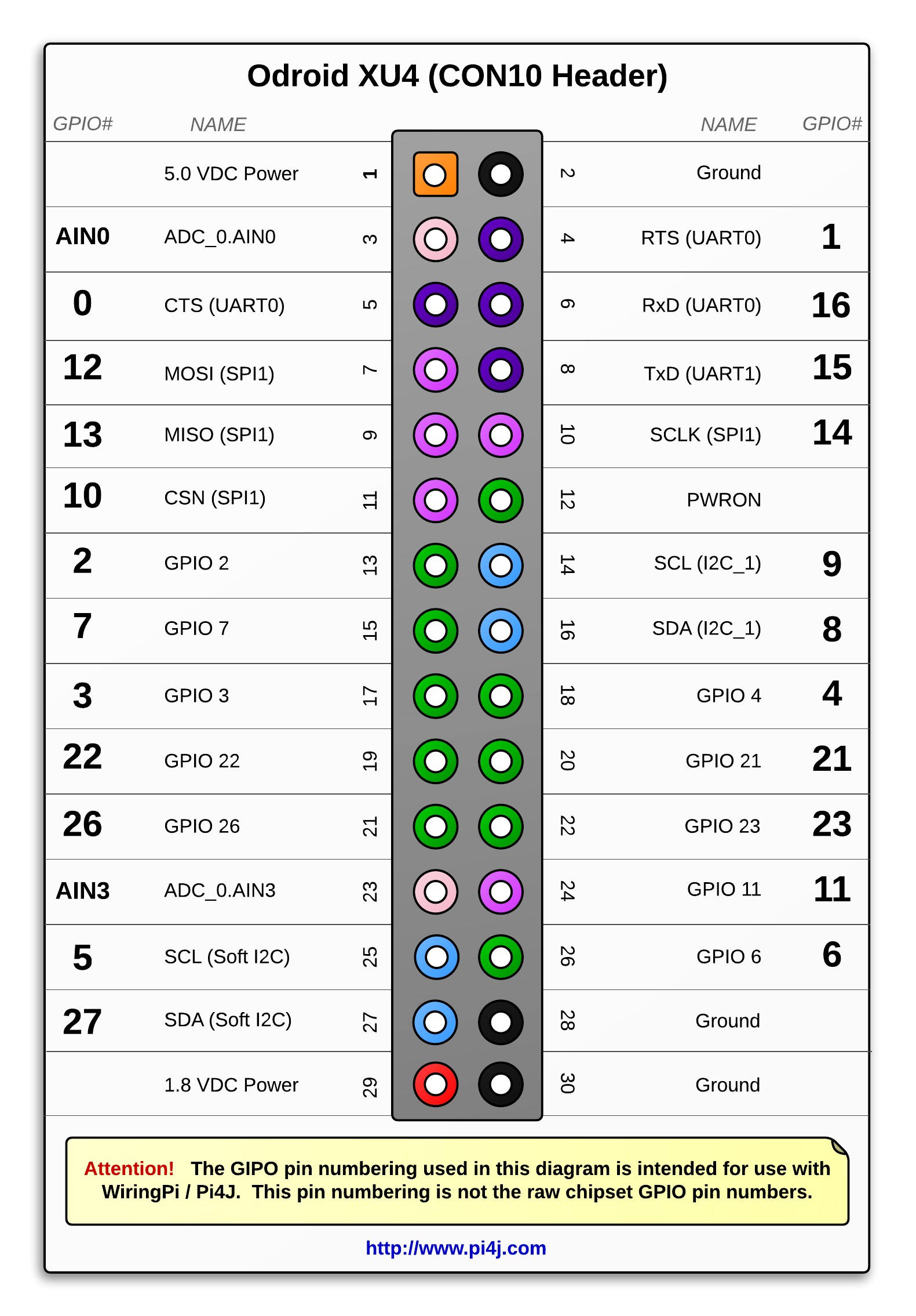
CON10 Pinout (30-pin Header)
The diagram below illustrates the GPIO pinout using the Pi4J/WiringPi GPIO numbering scheme for the CON10 header.
WARNING: All GPIO and AIN pins use 1.8VDC for signaling. Do not attempt to connect 3.3VDC or 5VDC to these header pins.
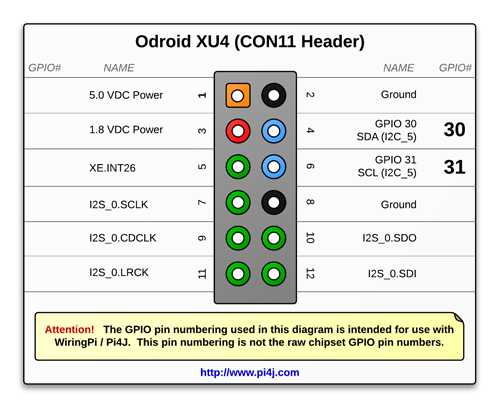
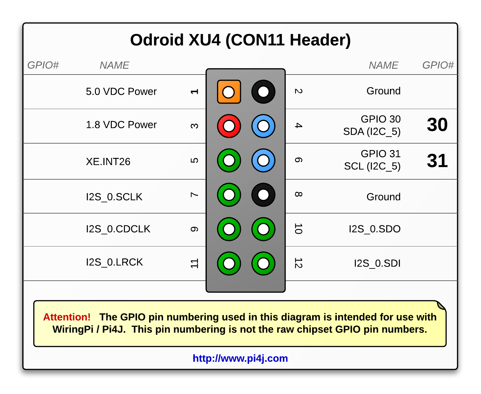
CON11 Pinout (12-pin Header)
The diagram below illustrates the GPIO pinout using the Pi4J/WiringPi GPIO numbering scheme for the CON11 header.
WARNING: All GPIO and AIN pins use 1.8VDC for signaling. Do not attempt to connect 3.3VDC or 5VDC to these header pins.
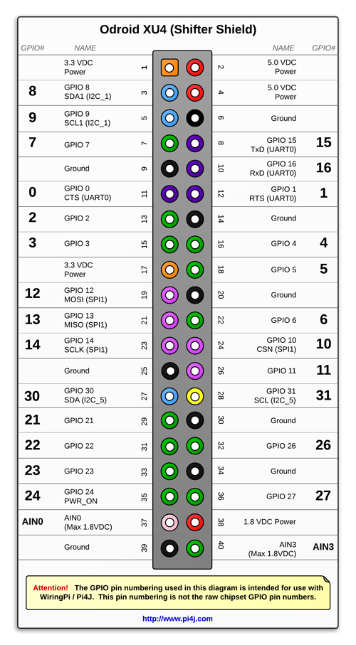
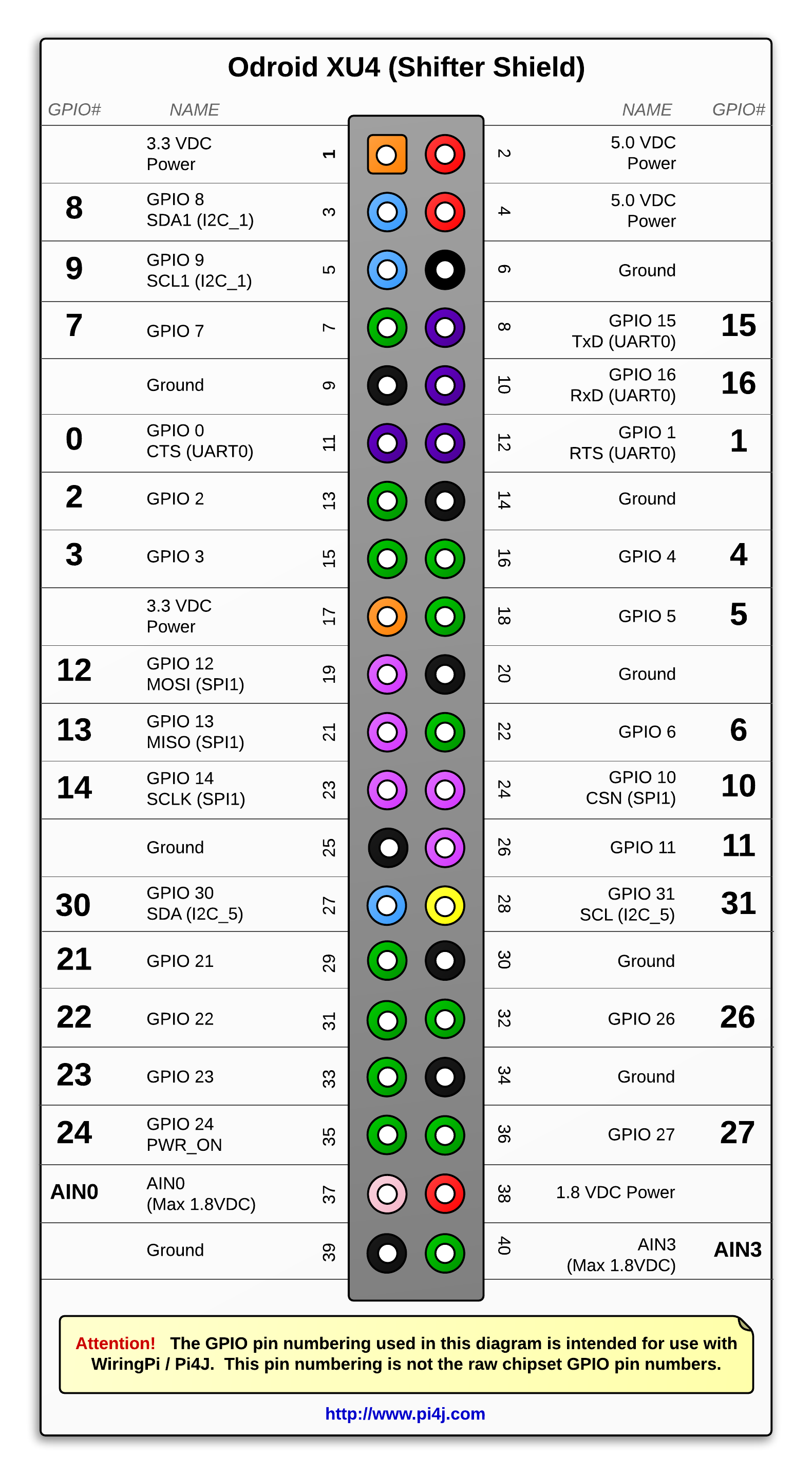
XU4 Shifter Shield Pinout (40-pin Header)
The diagram below illustrates the GPIO pinout using the Pi4J/WiringPi GPIO numbering scheme for the XU4 Shifter Shield GPIO 40-pin header.
Examples
A number of source code examples are provided to demonstrate the following capabilities/integrations:
- GPIO Input read current state for single pin
- GPIO Input event listener for a single pin
- GPIO Input event listener for all pins
- GPIO Output
- AIN (Analog Input) read current input value
- AIN (Analog Input) event listener
- I2C Communication
- SPI Communication
- Serial/UART Communication
- Software-based PWM
- System Info
Known Issues
- PWM
Hardware-based PWM is not supported on the Hardkernel Odroid XU4 board.
- WiringPi SoftPWM
SoftPWM is not supported on all Odroid GPIO pins on the C1/C1+/C2/XU4. This limitation is due to a GPIO pin mapping issue in the WiringPi port for Odroid by Hardkernel.
- SPI
SPI modes (other than the default SPI MODE 0) are not supported in the Hardkernel Odroid WiringPi port.
Additional Resources
- Please visit the usage page for additional details on how to control these pins using Pi4J.
- Click here for product information on the Odroid XU4
- Click here for more technical information on the Odroid XU4
- Click here for information on the Odroid XU4 Shifter Shield