


Pin Numbering - Odroid C1 / C1+
- Platform Configuration
- Numbering Scheme
- Expansion Headers
- GPIO Pinout (40-pin Header)
- Examples
- Known Issues
- Additional Resources
Platform Configuration
Unlike the RaspberryPi, to use the BananaPi board you must first configure the Pi4J library to use an alternate platform implementation.
There are three methods to configure the platform. You are free to use any of these three methods.
- Method 1 : Environment Variable
You can set the "PI4J_PLATFORM" environment variable to a value of "odroid".
- Method 2 : Java System Property
You can configure a Java system property named "pi4j.platform" to a value of "odroid".
- Method 3 : Inline Java Code
You can configure the platform in your Java code before you instantiate the Pi4J controller instance.
// ####################################################################
//
// since we are not using the default Raspberry Pi platform, we should
// explicitly assign the platform as the Odroid platform.
//
// ####################################################################
PlatformManager.setPlatform(Platform.ODROID);
Numbering Scheme
Pi4J uses an abstract pin numbering scheme to help insulate software from hardware changes.
Pi4J implements the same pin number scheme as the Wiring Pi project. More information about the WiringPi pin number scheme can be found here: http://wiringpi.com/pins/
Pi4J provides a OdroidC1Pin enumeration that is used to manage the accessible GPIO pins.
Expansion Headers
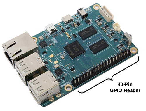
The Odroid C1 / C1+ board contains a 40-pin GPIO expansion header providing access to 19 GPIO pins and 2 AIN (analog input) pins. \
WARNING: The two AIN (Analog Input) pins use 1.8VDC. Do not attempt to connect 3.3VDC or 5VDC to these header pins.
(The GPIO header is illustrated below)
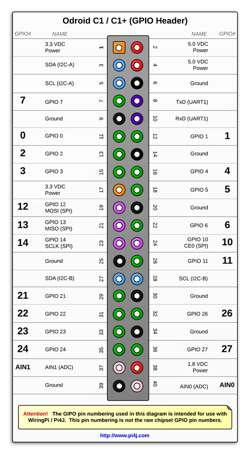
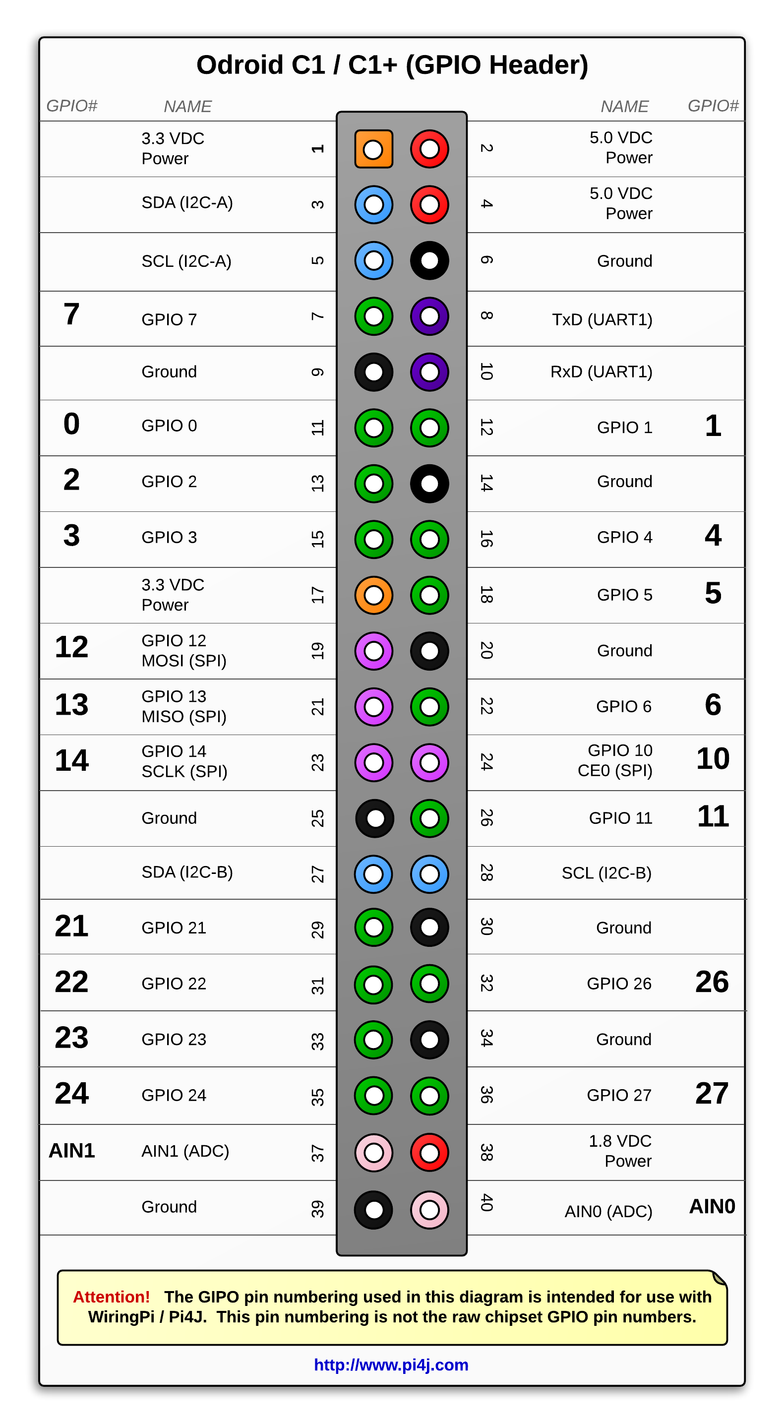
GPIO Pinout (40-pin Header)
The diagram below illustrates the GPIO pinout using the Pi4J/WiringPi GPIO numbering scheme.
WARNING: The two AIN (Analog Input) pins use 1.8VDC. Do not attempt to connect 3.3VDC or 5VDC to these header pins.
Examples
A number of source code examples are provided to demonstrate the following capabilities/integrations:
- GPIO Input read current state for single pin
- GPIO Input event listener for a single pin
- GPIO Input event listener for all pins
- GPIO Output
- AIN (Analog Input) read current input value
- AIN (Analog Input) event listener
- I2C Communication
- SPI Communication
- Serial/UART Communication
- Software-based PWM
- System Info
Known Issues
- GPIO Listener Events (edge triggered interrupts) [APPLIES ONLY TO C1/C1+/C2]
Pi4J uses edge detection for GPIO pin state change events. The Odroid C1/C1+/C2 only permit up to four GPIO pins to be configured with edge detection for both "rising" and "falling" edges (a.k.a., "both"). Thus, you can only use a maximum of four GPIO input pins with listener events. Alternatively, you can manually poll for GPIO pin state changes. The included sample code demonstrates both the event listener and polling for pin state changes:
GpioListenAllExample - PWM
PWM is not supported in the Hardkernel Odroid WiringPi port. Thus PWM is not currently supported by Pi4J for the Odroid C1/C1+/C2 boards.
- WiringPi SoftPWM
SoftPWM is not supported on all Odroid GPIO pins on the C1/C1+/C2/XU4. This limitation is due to a GPIO pin mapping issue in the WiringPi port for Odroid by Hardkernel.
- SPI
SPI modes (other than the default SPI MODE 0) are not supported in the Hardkernel Odroid WiringPi port.
Additional Resources
- Please visit the usage page for additional details on how to control these pins using Pi4J.
- Click here for more information on the Odroid C1/C1+.