


GPIO Triggers Example using Pi4J.
The following example demonstrates how to setup GPIO triggers. GPIO Triggers listen for pin state changes and then perform some action on on alternate GPIO pin or perform a callback to a user specified method. Pi4J includes several built in pre-defined trigger implementation classes or you can create your own trigger by implementing the GpioTrigger interface. Triggers are based on the GPIO listener implementation and rely on GPIO hardware interrupts not state polling.
Source Code
The source code for this example is included in the github repository:
https://github.com/Pi4J/pi4j-v1/tree/master/pi4j-example/src/main/java/TriggerGpioExample.java
/*
* #%L
* **********************************************************************
* ORGANIZATION : Pi4J
* PROJECT : Pi4J :: Java Examples
* FILENAME : TriggerGpioExample.java
*
* This file is part of the Pi4J project. More information about
* this project can be found here: http://www.pi4j.com/
* **********************************************************************
* %%
* Copyright (C) 2012 - 2016 Pi4J
* %%
* This program is free software: you can redistribute it and/or modify
* it under the terms of the GNU Lesser General Public License as
* published by the Free Software Foundation, either version 3 of the
* License, or (at your option) any later version.
*
* This program is distributed in the hope that it will be useful,
* but WITHOUT ANY WARRANTY; without even the implied warranty of
* MERCHANTABILITY or FITNESS FOR A PARTICULAR PURPOSE. See the
* GNU General Lesser Public License for more details.
*
* You should have received a copy of the GNU General Lesser Public
* License along with this program. If not, see
* <http://www.gnu.org/licenses/lgpl-3.0.html>.
* #L%
*/
import java.util.concurrent.Callable;
import com.pi4j.io.gpio.GpioController;
import com.pi4j.io.gpio.GpioFactory;
import com.pi4j.io.gpio.GpioPinDigitalInput;
import com.pi4j.io.gpio.GpioPinDigitalOutput;
import com.pi4j.io.gpio.PinPullResistance;
import com.pi4j.io.gpio.PinState;
import com.pi4j.io.gpio.RaspiPin;
import com.pi4j.io.gpio.trigger.GpioCallbackTrigger;
import com.pi4j.io.gpio.trigger.GpioPulseStateTrigger;
import com.pi4j.io.gpio.trigger.GpioSetStateTrigger;
import com.pi4j.io.gpio.trigger.GpioSyncStateTrigger;
/**
* This example code demonstrates how to setup simple triggers for GPIO pins on the Raspberry Pi.
*
* @author Robert Savage
*/
public class TriggerGpioExample {
public static void main(String[] args) throws InterruptedException {
System.out.println("<--Pi4J--> GPIO Trigger Example ... started.");
// create gpio controller
final GpioController gpio = GpioFactory.getInstance();
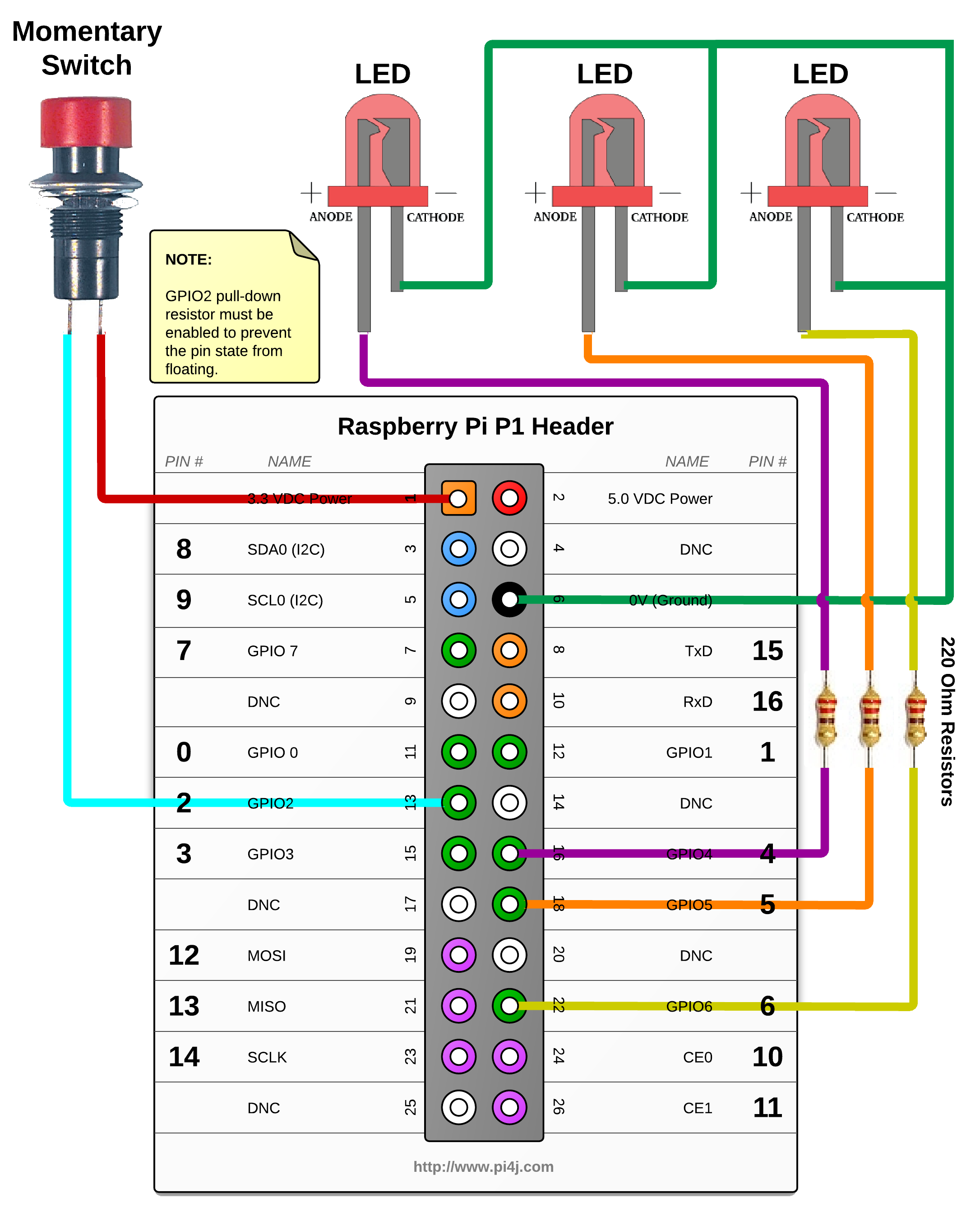
// provision gpio pin #02 as an input pin with its internal pull down resistor enabled
final GpioPinDigitalInput myButton = gpio.provisionDigitalInputPin(RaspiPin.GPIO_02,
PinPullResistance.PULL_DOWN);
System.out.println(" ... complete the GPIO #02 circuit and see the triggers take effect.");
// setup gpio pins #04, #05, #06 as an output pins and make sure they are all LOW at startup
GpioPinDigitalOutput myLed[] = {
gpio.provisionDigitalOutputPin(RaspiPin.GPIO_04, "LED #1", PinState.LOW),
gpio.provisionDigitalOutputPin(RaspiPin.GPIO_05, "LED #2", PinState.LOW),
gpio.provisionDigitalOutputPin(RaspiPin.GPIO_06, "LED #3", PinState.LOW)
};
// create a gpio control trigger on the input pin ; when the input goes HIGH, also set gpio pin #04 to HIGH
myButton.addTrigger(new GpioSetStateTrigger(PinState.HIGH, myLed[0], PinState.HIGH));
// create a gpio control trigger on the input pin ; when the input goes LOW, also set gpio pin #04 to LOW
myButton.addTrigger(new GpioSetStateTrigger(PinState.LOW, myLed[0], PinState.LOW));
// create a gpio synchronization trigger on the input pin; when the input changes, also set gpio pin #05 to same state
myButton.addTrigger(new GpioSyncStateTrigger(myLed[1]));
// create a gpio pulse trigger on the input pin; when the input goes HIGH, also pulse gpio pin #06 to the HIGH state for 1 second
myButton.addTrigger(new GpioPulseStateTrigger(PinState.HIGH, myLed[2], 1000));
// create a gpio callback trigger on gpio pin#4; when #4 changes state, perform a callback
// invocation on the user defined 'Callable' class instance
myButton.addTrigger(new GpioCallbackTrigger(new Callable<Void>() {
public Void call() throws Exception {
System.out.println(" --> GPIO TRIGGER CALLBACK RECEIVED ");
return null;
}
}));
// keep program running until user aborts (CTRL-C)
while (true) {
Thread.sleep(500);
}
// stop all GPIO activity/threads by shutting down the GPIO controller
// (this method will forcefully shutdown all GPIO monitoring threads and scheduled tasks)
// gpio.shutdown(); <--- implement this method call if you wish to terminate the Pi4J GPIO controller
}
}
JavaDoc
The following JavaDoc links are the primary interfaces used to setup triggers for GPIO state changes:
- com.pi4j.io.gpio.GpioFactory
- com.pi4j.io.gpio.Gpio
- com.pi4j.io.gpio.GpioPin
- com.pi4j.io.gpio.PinEdge
- com.pi4j.io.gpio.PinState
- com.pi4j.io.gpio.PinResistor
- com.pi4j.io.gpio.trigger.GpioCallbackTrigger
- com.pi4j.io.gpio.trigger.GpioPulseStateTrigger
- com.pi4j.io.gpio.trigger.GpioSetStateTrigger
- com.pi4j.io.gpio.trigger.GpioSyncStateTrigger

Navigate
If you have not already downloaded and installed the Pi4J library on the RaspberryPi, then view this page for instructions on where to download and how to install Pi4J:
Download & Install Pi4J
First, locate the TriggerGpioExample.java source file in the samples folder of the Pi4J installation on the RaspberryPi.
You can use the following command on the Pi's console or SSH terminal to navigate to this path:
cd /opt/pi4j/examples
Compile
Next, use the following command to compile this example program:
javac -classpath .:classes:/opt/pi4j/lib/'*' -d . TriggerGpioExample.java
Execute
The following command will run this example program:
sudo java -classpath .:classes:/opt/pi4j/lib/'*' TriggerGpioExample
Output
The LED attached to GPIO pin 21 should turn ON when the momentary button is pressed and OFF when the button is released.
The LED attached to GPIO pin 22 should turn ON when the momentary button is pressed and OFF when the button is released.
The LED attached to GPIO pin 23 should turn ON for 1 second when the momentary button is pressed. The button release has no effect on this LED.
The following message should be displayed on the console each time the momentary button is pressed and again when released.
--> GPIO TRIGGER CALLBACK RECEIVED