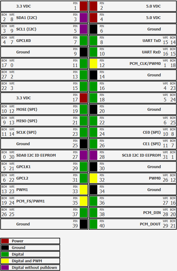
Understanding the GPIO pins
Connecting electronic components to the Pi is done via one or more of the pins in the so-called header. The number of pins has “grown” between the different Raspberry Pi board versions, but all recent ones have a 40-pin header. It’s of course important to be aware of the correct numbering to not connect components the wrong way.

Type of Pins
The pins have different uses
Power and Ground
Both 5V and 3.3V are available as power pins and, of course, also ground pins. Anytime the board is powered you have a fixed power supply available for your components. You have to take into account not to connect devices that need a lot of current, otherwise the Raspberry Pi itself will not behave as expected and reboot for instance.
Digital GPIO
The other ones are “General-Purpose Input/Output” (GPIO) pins. These pins can be addressed with software to act as input or output for an application. They use 3.3V, meaning an output pin will be set to 0V (low) or 3.3V (high) and an input pin will read 0V as low and 3.3V as high.
Most of the GPIOs have an internal pull-up or pull-down resistor which can be enabled in software.
Many electronic components need a different voltage level! For instance, some components created for Arduino, operate on 5V. They will not work reliably with a Raspberry Pi as the GPIOs only provide or expect 3.3V. If you need to connect components with a different voltage, you’ll need to use a “Level Shifter”, for instance: Adafruit QT 3V to 5V Level Booster Breakout.
Overview
The following image gives you an overview of the pins and types of a typical 40-pin header. Note the different numbers being used:
- PIN: 1 to 40 logical order of the pin
- BCM: the number to be used in your Java code to specify the GPIO to be used. BCM refers to the “Broadcom SOC channel” number, which is the numbering inside the chip which is used on the Raspberry Pi. These numbers changed between board versions as you can see in the previous tables for the 26-pin header type 1 versus 2, and or not sequential.
- WPI: WiringPi number which was used by V1 of Pi4J. The WiringPi numbering has a “historical reason”. When development for the very first Raspberry Pi’s was ongoing, only 8 pin-numbers were foreseen. But, when the designs further evolved and more pins were added, the numbering in WiringPi was extended to be able to address the extra pins.
