Electrical Engineering
The goal of the Pi4J project is to combine sofware (Java) with hardware (electronic components). On this page we give you some tips and tricks for the electronics part.
Breadboard
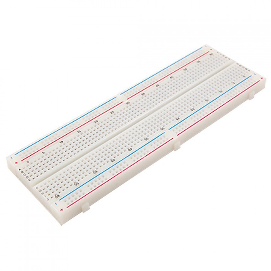
A breadboard is the basic for each experiment. It allows you to easily connect several components to each other and the Raspberry Pi. Here is a video that explains the basics of breadboards:
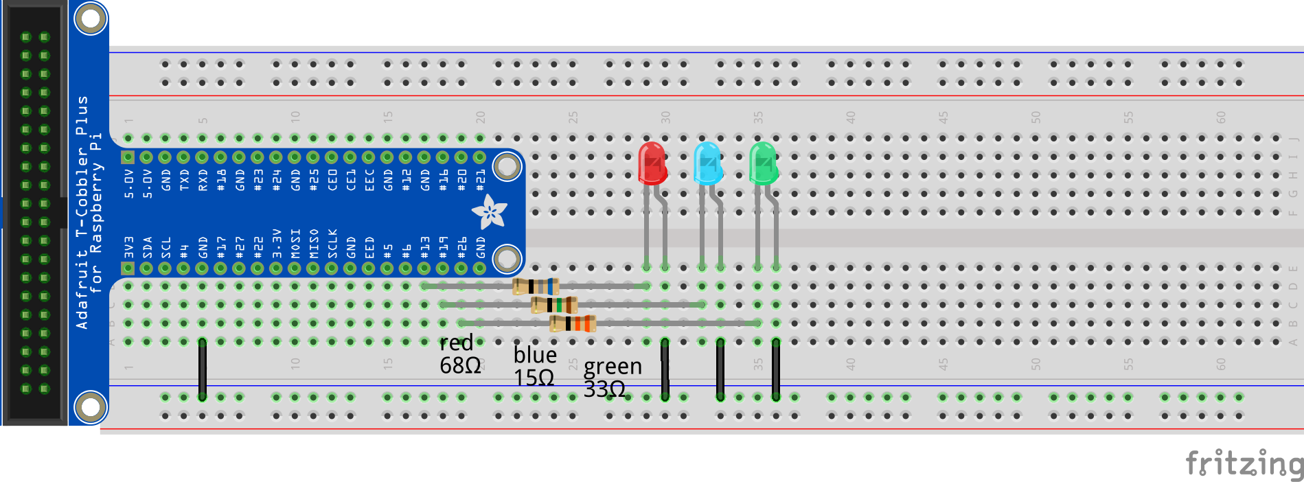
The red and blue lines on the side show which pins are connected. Be aware that red and blue can also be swapped, because not all suppliers use them in the same position.
On some boards these lines are interrupted in the middle (see picture breadboard).
This means at this point, the pins are interrupted and not electrically connected.
Resistor Dimensioning
Resistors can be used for different effects. One application is to improve the stability of the application with PullUp and PullDown resistors. Another application is to use resistors to protect the PI against voltage peaks or short circuit currents.
PullUp PullDown
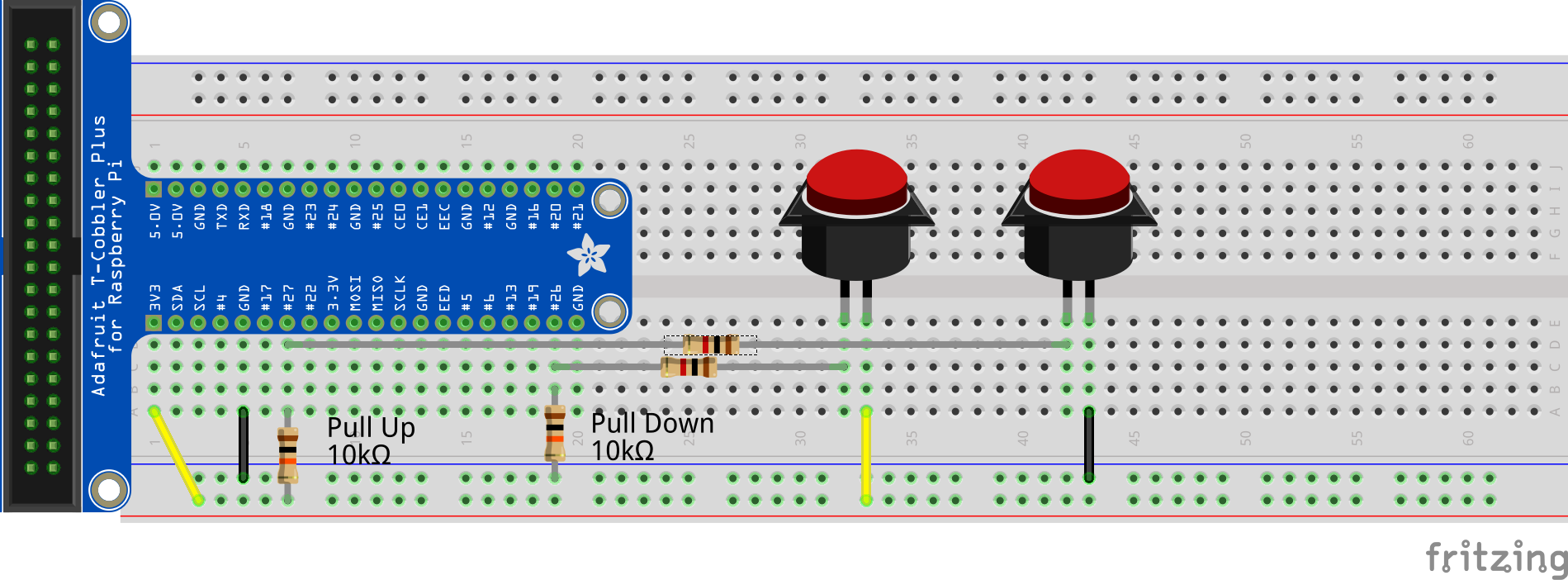
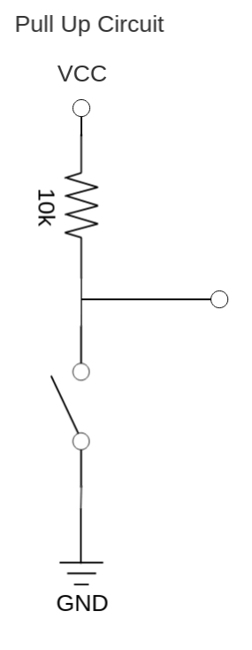
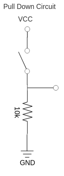
In electronic logic circuits, a pull-up resistor or pull-down resistor is a resistor used to ensure a known state for a signal. It is typically used in combination with components such as switches and transistors, which physically interrupt the connection of subsequent components to ground or to VCC. Closing the switch creates a direct connection to ground or VCC, but when the switch is open, the rest of the circuit would be left floating (i.e., it would have an indeterminate voltage).
For a switch that is used to connect a circuit to VCC (e.g., if the switch or button is used to transmit a “high” signal), a pull-down resistor connected between the circuit and ground ensures a well-defined ground voltage (i.e. logical low) across the remainder of the circuit when the switch is open. For a switch that is used to connect a circuit to ground, a pull-up resistor (connected between the circuit and VCC) ensures a well-defined voltage (i.e. VCC, or logical high) when the switch is open.
The size of the resistor can vary between 1kOhm and 100kOhm. Here it is necessary to weigh what is useful for the application. The closer the resistor is to 0, the stronger the level is defined, but the greater the current consumption in the open state. The higher the resistance, the less current is consumed in the off state, but the more unstable the signal becomes. For a start value PullUp and PullDown resistors with 10kOhm are to be used.
Voltage Divider
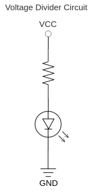
If components have a lower operating voltage than the 3.3V of the Raspberry Pi, a voltage divider can be used to achieve the desired voltage. For example, a red LED has an operating voltage of 1.8V. This means that 1.5V must drop across a second load. If we assume that the LED needs 20mA of current, this means that we should connect a resistor of 75 Ohm in series to the LED.
If the required current and the required voltage of the load are known, the exact required resistance can be calculated here.
3.3V <–> 5V Level Shifter
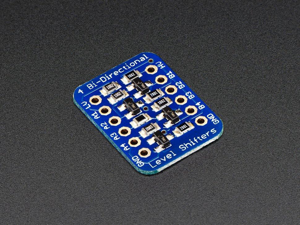
To protect the Pi from 5V devices, a level shift/conversion can be done with the “Adafruit TXB0104 Bi-Directional Level Shifter” component. The bi-directional level shifter works for an I2C bus, for a TTL serial connection, for a slow <2MHz SPI connection and any other digital interface both uni- and bidirectional.
Additional Power Supply
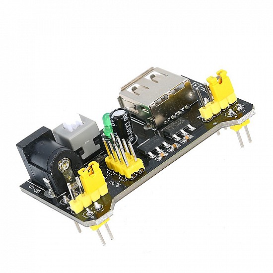
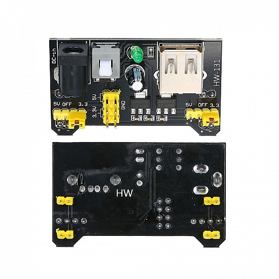
If one or more large loads are required for the project, it may be necessary to use an additional power supply. A solution for this is the Mini Power Supply Module HW-131 Breadboard Power Module which provides two voltages 3.3V and 5V and a maximum output current of 700mA.
Do not use the USB port of the computer to power the electronics. Errors in the wiring can destroy the USB port of the computer.
In case of an additional power supply, the ground of the Raspberry Pi and the ground of the power supply must be connected to each other.
Soldering Tutorial
A video that explains the basics of soldering:
A video that explains how to remove solder:
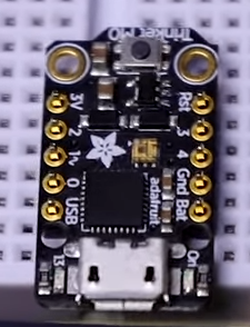
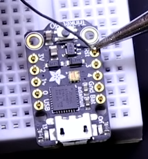
If a breakout with two pin headers like the TXB0104 is used, the pin headers can be mounted on the breadboard first, then the breakout is placed on the pin headers and finally everything can be soldered. So the pin headers are mounted exactly in 90° angle to the breakout and can be mounted on the breadboard without any problem.
Automatic Wire Stripper
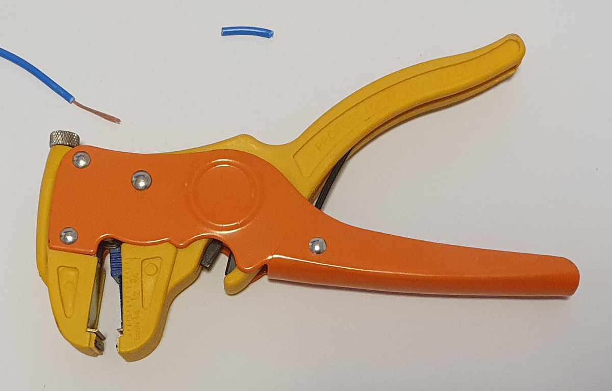
A video that explains how the automatic wire stripper works:
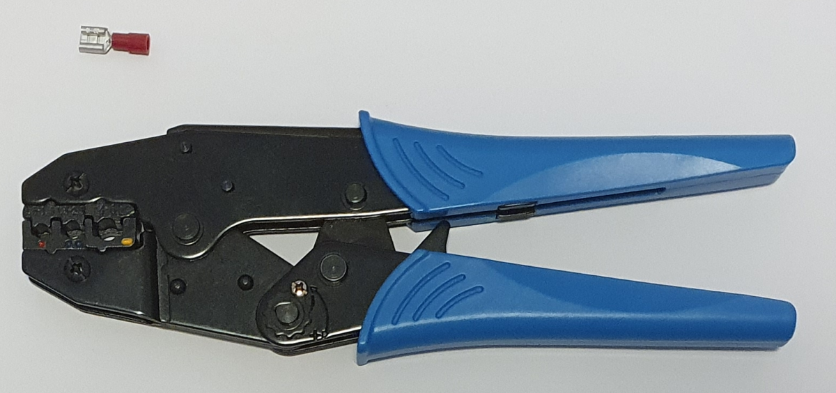
Crimping Tutorial
A video that explains the basics of crimping wires:
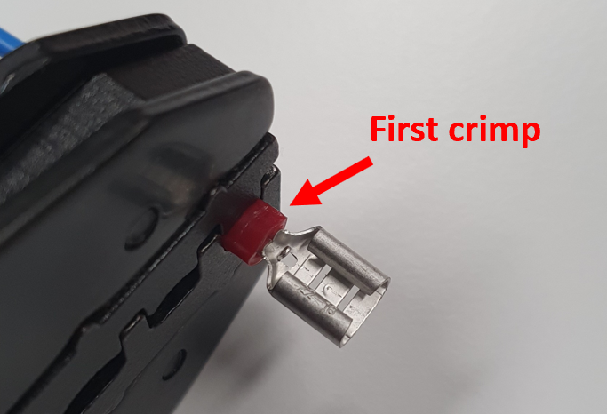
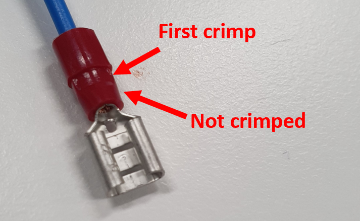
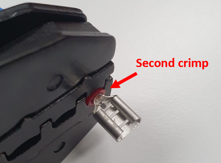
If the crimp connection does not hold, the following measures can lead to a better connection:
- Strip wire to double length, lay on top of each other and twist (see picture below)
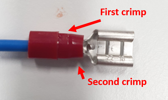
- The crimping tool is too short, crimp the sleeve twice in different places (see picture below)
Crimping Ferrules Tutorial
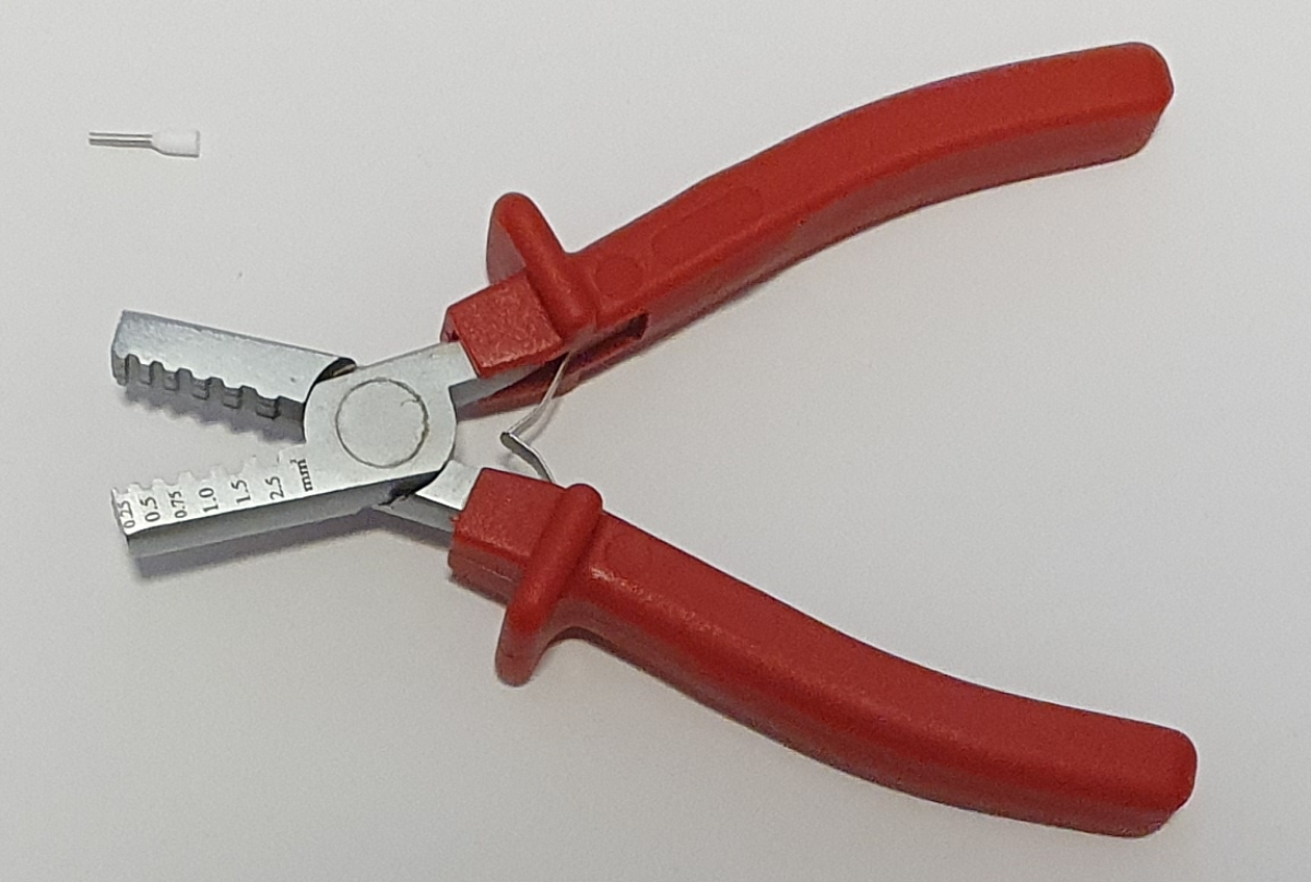
A video that explains the basics of crimping ferrules to wires:
