JMonkeyEngine with Joystick
Pavl G. created a Java Gradle library to control a car in a JMonkeyEngine game with an arduino joystick module connected to a Raspberry Pi4 model B, using GPIO digital pins and SPI interfacing through MCP3008 ADC (Analog~Digital Converter).
Requirements
- Raspberry Pi with arm processor (pi3, pi4, piZero) with a working java8 (preferred).
- Female-to-male jumper wires.
- Breadboard.
- Arduino Joystick module.
- MCP3008 IC (ADC – other adcs may work too, but we are covering only MCP3008 here).
- Some patience and time.
Difference between Analog and Digital signals?
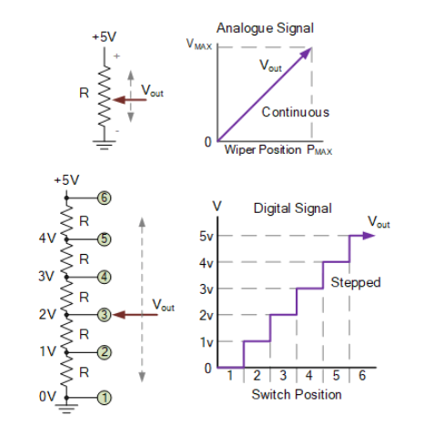
- An analog signal is a continuously variable voltage between 0 and Vmax over time, examples : Temperature sensor output, Potentiometers (joysticks)….
- A digital signal is rather a discrete step-by-step output voltage of LOW (fall) to HIGH (rise) according to the switch position among a network of resistors.
- To convert from analog signals to digial signals, we need to encode the output voltage changing over time to some sequence of bits.
- We cannot interface analog electronics on digital devices such as (arduinos and raspberry pi w/o converting into digial signals).
What’s ADC?
Let’s have an example of a 3-bit Analogue to Digital Converter :
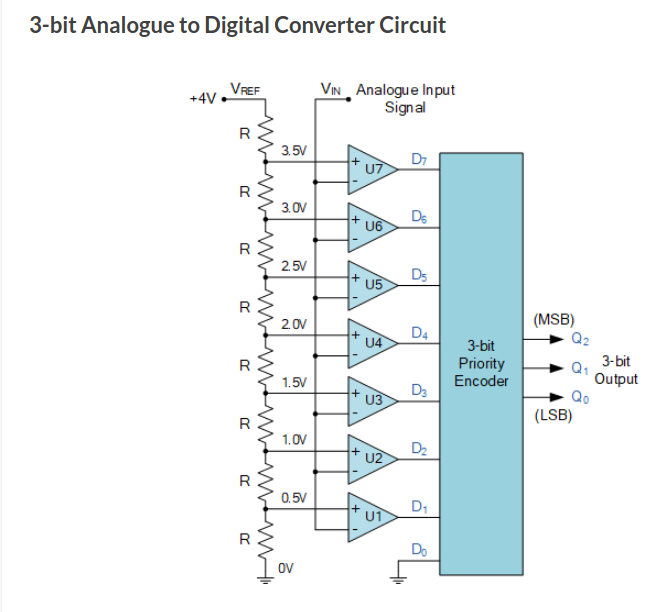
This is how ADC works under the hood, steps of converting Analog to Digital
- Analog voltage goes through
Vin, - Then it’s passed to a network of voltage comparators that compares its voltage to the selected reference range (Vref, which is selected at the time of wiring).
- If
Vin>Vrefthe comparator output would be HIGH aka (1), ifVin<Vrefthe comparator output would be LOW aka (0). - The significant of having a network of comparators is to encode the value of the analog signal into a digital sequence of bits.
- The output of comparators
Dngets passed into a 3-bit priority encoder. - The priority encoder by definition, it encodes based on the high priority input and ignores the low priority input.
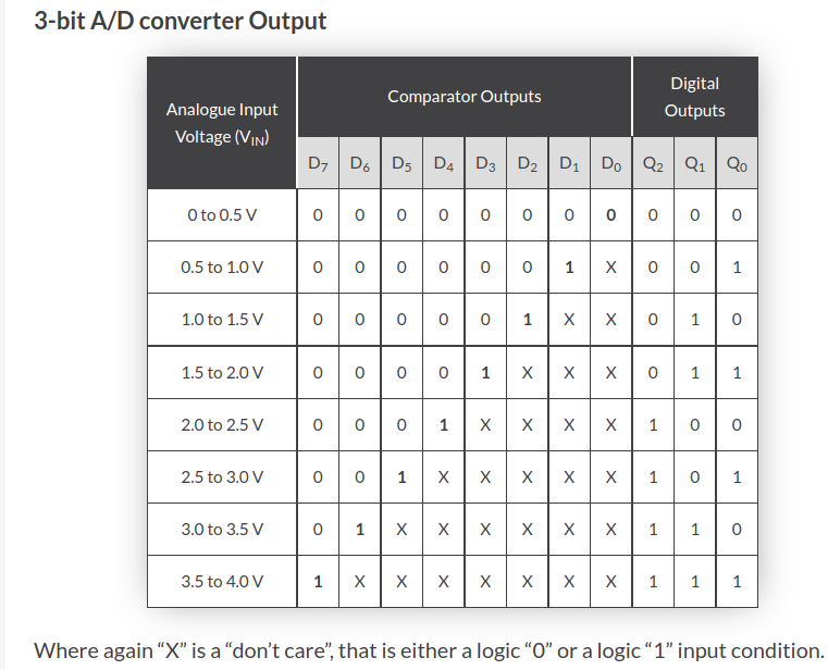
- So, if
Vin = 3.5 to 4.0 Vthen theComparators output = 11111111, - At last when inputting the comparator output into the priority encoder the encoder gives a value of 7 which points to D7 of comparator U7 aka the last voltage level, and that’s true because our Vin is bigger than the Vref
.
What’s SPI?
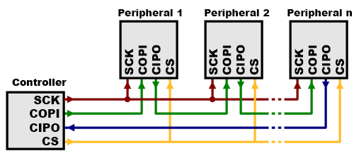
- Serial Peripheral Interface (SPI) is an interface bus commonly used to send data between microcontrollers and small peripherals such as shift registers, sensors, and SD cards. It uses separate clock and data lines, along with a select line to choose the device you wish to talk to.
- Our target is to transfer the output from our priority encoder to the BCM processor of our Pi throughout the SPI protocol (Synchronously over Tx from MCP3008 to Rx of the Pi).
- To send and receive synchronous data we use
MISO(the same as CIPO) for receving data from peripherals andMOSI(the same as COPI) to send data to the peripherals. - MISO : Master-in-Slave-Out = CIPO : Controller-in-peripheral-out.
- MOSI : Master-out-Slave-In = COPI : Controller-out-Peripheral-in.
- MCP3008 is used to receive analog input, so MISO or CIPO is our common active data line.
- CS is the chip select, it’s used to select which peripheral device to use.
- SCLK is the serial clock and it’s used to synchronize data on a data line, to have a clear separate message per 8 clocks (8-bit message).
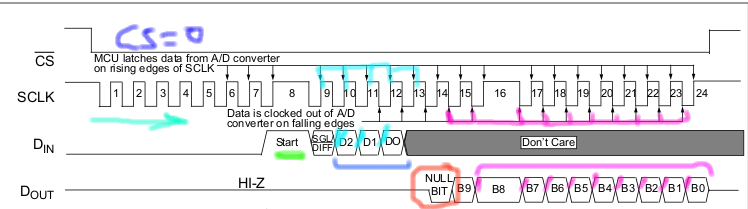
This diagram describes steps of how SPI Communication works in MCP3008 :
- CS = LOW -> signifies the selection to peripheral IO 0.
- SCLK += Clock.
- Rising edge of clock (LOW-to-HIGH) -» Reads data from A/D and latches it for the MCU (micro-controller unit) -» Creates the rising edges of
Dinline (Cyan line) -» MOSI line. - Falling edge of clock (HIGH-to_LOW) -» Writes data from the MCU to the A/D -» Creates the falling edges of
Doutline bits (magneta line) -» MISO line. - Each input (D0, D1, D2, Dn) is an analog input that’s encoded into a 10-bit digital output (B0-B9) and then clocked out for the MCU on the falling edge of the SCLK as shown by the last data line (Dout).
B-null (red circle)is the leading bit, it marks the last bit clocked out.
MCP3008 ADC
- MCP3008 A/D Converter is a 10-bit analog to digital converter.
- 10-bit means : it has a maximum resolution of 10-bits
in binary (1111111111)=in dec (1023)=in hex (3FF)and that’s determined by the Vref vs Dn voltage as discussed before using the voltage comparator. - MCP3008 has 8 analog input channels that can be used in parallel (updated via SCLK using the SPI), the last number
8stands for the number of analog inputs. - MCP3008 controls its logic using SPI.
- MCP3008 can accept between
2v7and5v5after which the IC may burn out. - MCP3008 comes in various packages for various usages (PDIP, SOIC,….), in our case we would use the PDIP.
- Other adcs like
MCP3002andMCP3004works by the same analogy, except that they can accept a max of 2 analog inputs and a max of 8 analog inputs respectively, if your project would use a max of 2 analog inputs, then you could buyMCP3002and still can follow this tutorial.
Cracking the MCP3008 Datasheet
Alright, here is how to tackle down the MCP3008/MCP3004 datasheet :
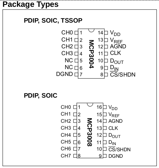
Know your package type whether PDIP (Plastic Dual in-Line), SOIC (Small Outline IC), TSSOP (Thin Shrink Small Outline Plastic) :
Know your pin configuration and orientation :
- In our case, we do a tutorial, so we will use PDIP (Plastic-Dual-In-Line) package :
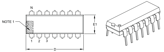
- So, our pins outline are as follows :
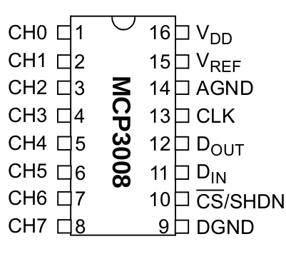
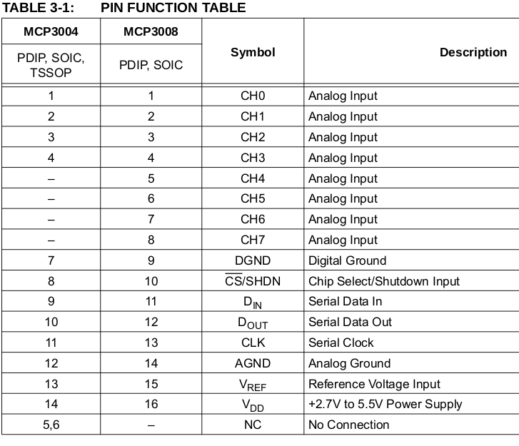
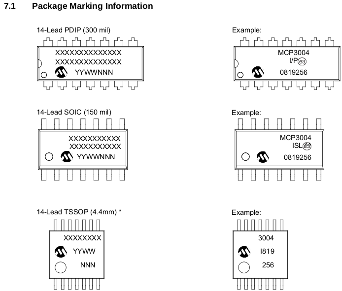
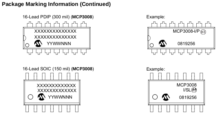
Know the meaning of pins on your package :
This is the hardest part of understanding how an IC work, but quick looking on an internal diagram may be insightful :
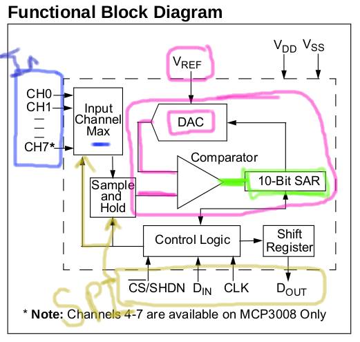
As you can see the MCP has a different way of comparing VREF and Din and encoding the results, it uses a modern way called
10-bit SAR - Successive Approximation Register and a DACwhich we will not cover in this tutorial but the net result is the same as a using a network of resistors with comparators.Know the max ratings of various IC properties before wiring up :
- VDD-Max-Rating = 5v5.
- VREF-Max-Raing = 5v5, min-working-voltage = 2v7.
- Analog-Channel-Max-Rating = VREF = 5v5 – after that the channel may burn or the IC may not work.
- Max-Clock-Rating = f-CLK = 3.6 MHZ on 5v5, 1.35 MHZ on 2v7.
- Error = +/- 1.0 LSB (least significant bit).
- Resolution = max analog value = 10-bits = 0b1111111111 = 1023.
- Other data like CLK rising, falling and setup time are neglectable.
- You may pay attention to temperature data if your project works in a special temperature case like a hot place or freezer or etc.
Have some fun with the IC.
Wiring Up
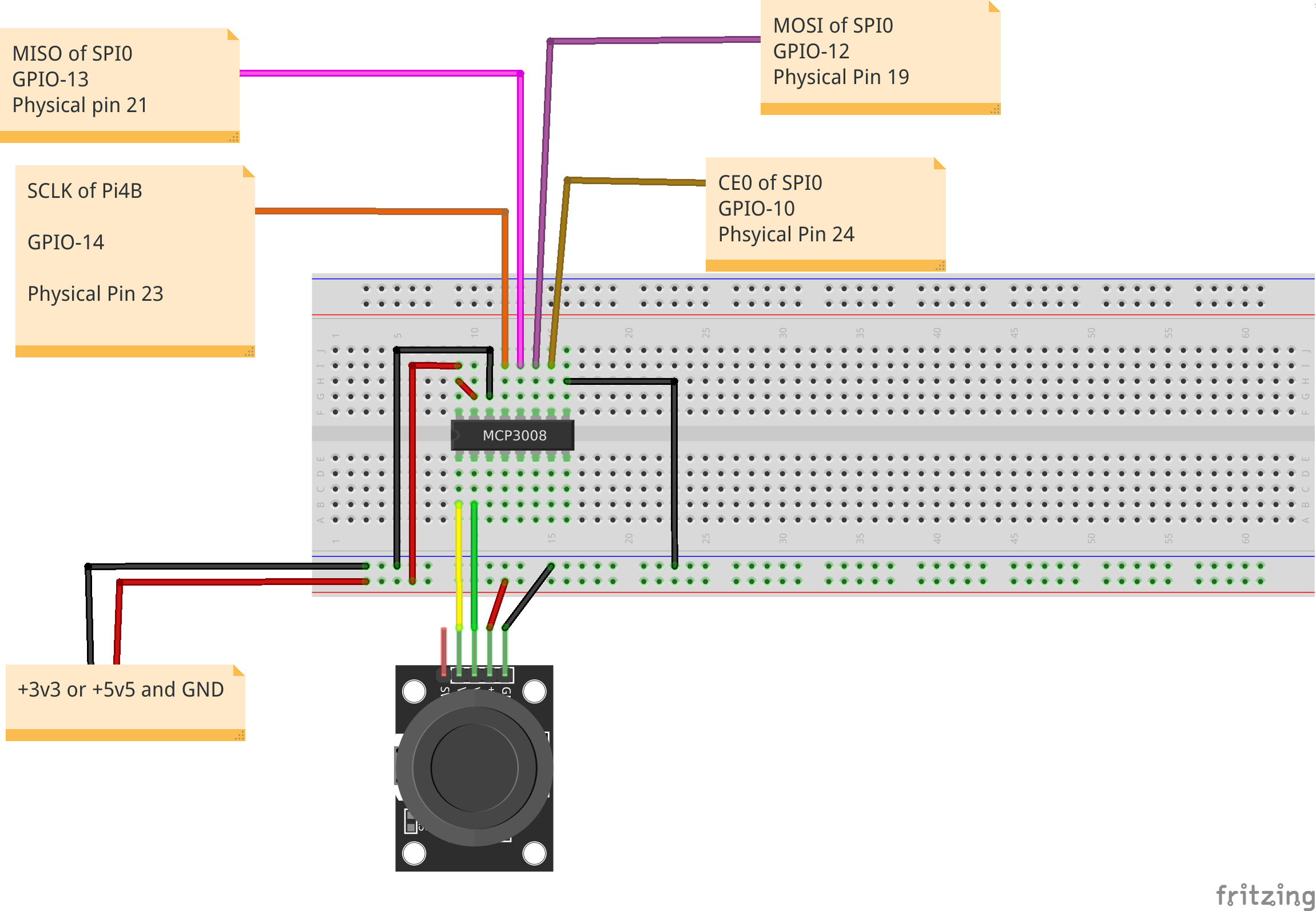
- Vcc : is used for powering up the IC and not to compare with VREF.
- Vref : is used for controlling the maximum resolution of the input voltage (analog signal), if VREF = 5v5 (maximum voltage received by MCP3008), then the resolution of Vin is a 100%.
Testing the wiring
Before going deeper and testing with jme vehicle, please test this code and do your conclusions :
// Define MCP3008 provider on CS0 -- Peripheral device 0
final MCP3008GpioProvider mcp3008GpioProvider = new MCP3008GpioProvider(SpiChannel.CS0);
// define analog input pins on the adc
final GpioPinAnalogInput[] gpioPinAnalogInput= new GpioPinAnalogInput[2];
gpioPinAnalogInput[0] = MCP3008Pin.CH0;
gpioPinAnalogInput[1] = MCP3008Pin.CH1;
// define the threshold analog (the minimum voltage at which the Pi can listen to).
mcp3008GpioProvider.setEventThreshold(thresholdAnalogValue, gpioPinAnalogInput);
// enable monitoring of analog values with an interval of 250 ms
mcp3008GpioProvider.setMonitorEnabled(true);
mcp3008GpioProvider.setMonitorInterval(250);
// start collecting data from the SPi connected to MCP3008 output.
final GpioController gpioController = GpioFactory.getInstance();
gpioController.addListener((GpioPinListenerAnalog) event -> {
    System.out.println("Value at CH0 : " + mcp3008GpioProvider.getValue(gpioPinAnalogInput[0]));
    System.out.println("Value at CH1 : " + mcp3008GpioProvider.getValue(gpioPinAnalogInput[1]));
}, gpioPinAnalogInput);
Testing with a jmonkeyengine vehicle
It’s very hard to give you a full overview of how to create a jmonkeyengine vehicle in this tutorial, so you could fairly refer to jme docs and examples for more :
- Use the physics in your game and control your game via keyboard : https://wiki.jmonkeyengine.org/docs/3.4/tutorials/beginner/hello_physics.html
- A Keyboard controlled car demo : https://github.com/jMonkeyEngine/jmonkeyengine/blob/master/jme3-examples/src/main/java/jme3test/bullet/TestPhysicsCar.java
- The idea is simple, any game can be controlled using a keyboard interface (bound to jme update), so you can simply replace that with a custom
InputHandlerusing a custom hardware. - The trick is to bind your joystick pi4j interface to jme thread (OpenGL’s thread).