Prototype Board
A Versatile Prototype Board
Experimenting with various ICs ‘chips’ may require different methods to connect the chip to the Pi. As shown in the BMP280 usage a chip maybe available mounted on a small circuit board where connection to the Pi requires only jumpers. But even this simple means has limits as connecting several chips when using a Pi case and maybe a cooling fan creates problems. In addition some chips are only available as a socket device where a 4-28 pin socket is required. This next section demonstrates ‘a’ way these limits can be overcome.
Connecting to the Pi
The use of breadboards adds flexibility in the ways to install and jumper to various chips. After soldering the pins to the chip breadboards you can use female-female jumpers to connect directly to the Pi Gpio pins from more than one chip breadboard.
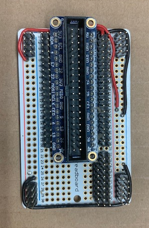
Also, the jumper connections to the Pi are simplified by extending the Pi gpios to an external Gpio breadboard.
Power off the Pi with sudo shutdown prior to making connections.
Component and wiring
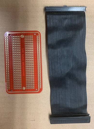
Ribbon Cable
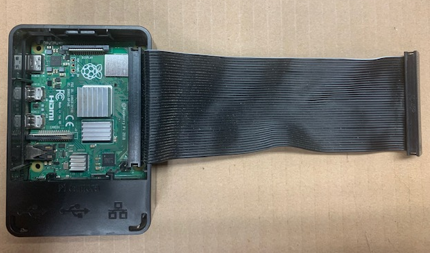
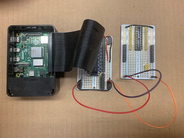
Connecting directly to the Pi 40 pin connector becomes difficult as the number of terminations increase and the use of a case and fan require minor disassembly. The 40 pin connector can be extended to a Gpio breadboard. This extension is possible with a ribbon cable.
Once the ribbon cable is attached to the Pi 40 pin connector the Pi case can be secured.
Ribbon cable termination
Using a 40 pin connector labeled for a Pi facilitates installing jumpers. The Gpio breadboard terminates the ribbon cable. The Gpio breadboard is wired to supply 3.3v 5v and ground through multiple pins to facilitate use of multiple chip breadboards.
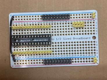
The use of a 28 pin socket will accommodate many different chips.
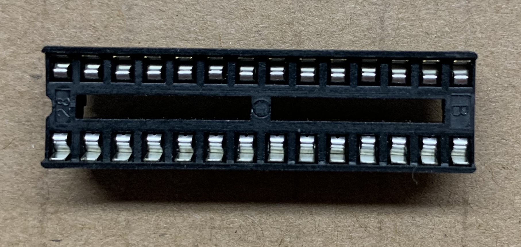
Soldering the 28 pin socket and pins associated with each of the 28 pins provides jumper connections to all pins of the inserted chip.
The chip breadboard also provides sets of pins for 3.3v 5v and ground. Single jumpers from the Gpio breadboard to this chip breadboard provides these multiple pins.
Complete
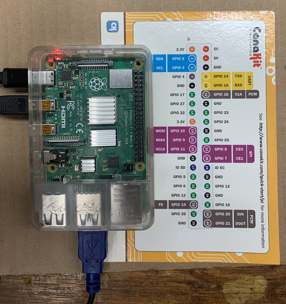
At this point a chip can be plugged into the 28 pin connector. If you insert the chip with its pin 1 at the pin 1 of the chip breadboard it simplifies pin identification between the chips datasheet and its breadboard connection. Using the chips Datasheet jumpers connect between pins of the chip to the Pi GPIOs on Gpio breadboard connector or 5v/3.3v and ground on the chip breadboard.