PWM Hardware Support on RPi5
2024-04-23, by Tom Aarts
The next version of Pi4J (are now already in 2.5.2-SNAPSHOT) will add PWM support via a new provider linuxfs-pwm. The previous PWM PiGpio provider does not support the Raspberry Pi 5 RP1 chip. To use this new provider, changes are required in your pom.xml dependencies and Java code. The details of using this new provider are explained in the Pi4J documentation in Pulse Width Modulation. In this blog post, I want to provide extra details and an example implementation. This post reference changes when using the Bookworm OS on a Raspberry Pi 5. If you are using the linuxfs-pwm provider on a Raspberry Pi 4, consult the Pulse Width Modulation for config.sys and channel differences.
With this new version of Pi4J, additional improvements of the PWM integration are improved, based on this discussion “java.nio.file.AccessDeniedException: /sys/class/pwm/pwmchip0/pwm0/duty_cycle” on the Raspberry Pi Forum.
What Changes Are Required
- Update pom.xml dependencies to add the
linuxfsprovider. - Modify
config.txt: after deciding which GPIO you want to present the PWM, the requireddtoverlaystatement must be added as described below. - Reboot the Raspberry Pi5 to enable the
config.txtmodification. - Modify the java application to use the new provider and set the address.
- Connect LED.
- Run the sample program.
Update pom.xml
You projects pom.xml requires an additional dependency.
<dependency>
    <groupId>com.pi4j</groupId>
    <artifactId>pi4j-plugin-linuxfs</artifactId>
    <version>${pi4j.version}</version>
</dependency>
Modify config.txt
Modification of this files requires `sudo. In addition, while opening the file to edit OS settings, will display a warning that an error in this file might prevent successful reboot. Consider if you want to backup your system.
These are optional values to place into the file. Only one item should be added. Which one you use is based upon whether you want one or two GPIOs for PWM, and which GPIO(s) you want to use.
The selected value dtoverlay must be placed after the [all] statement.
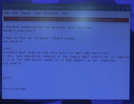
- One active PWM on GPIO 18, this is channel 2, so the address attribute will be 2:
[all]
dtoverlay=pwm
- Two active PWMs. First one on GPIO 18, this is channel 2 (= address attribute 2). The other active PWM on GPIO 19, this is channel 3 (= address attribute 3):
[all]
dtoverlay=pwm-2chan
- Two active PWM. First one on GPIO 12, this is channel 0 (= address attribute 0). The other active PWM on GPIO 13, this is channel 1 (= address attribute 1).
[all]
dtoverlay=pwm-2chan,pin=12,func=4,pin2=13,func2=4
For example, see screenshot on how to edit config.sys to set to a single PWM GPIO18:
Reboot
- Close your open applications.
- Enter:
sudo shutdown -r. This will terminate all remaining applications and reboot.
Modify the application
- Your system is now ready to use the
linuxfs-pwmprovider. - Previously the application’s `PwmConfigBuilder address was the GPIO number, but now you need to use the channel number as the address parameter.
package com.pi4j.test.devices.pwmTest;

import com.pi4j.Pi4J;
import com.pi4j.context.Context;
import com.pi4j.io.pwm.Pwm;
import com.pi4j.io.pwm.PwmType;
import com.pi4j.util.Console;

import java.util.Scanner;

public class UserTest {
    private static Pwm pwm = null;
    private static Context pi4j;

    public static void main(String[] args) throws Exception {
        pi4j = Pi4J.newAutoContext();

        var console = new Console();
        System.out.println("----------------------------------------------------------");
        System.out.println("PI4J PROVIDERS");
        System.out.println("----------------------------------------------------------");
        pi4j.providers().describe().print(System.out);
        System.out.println("----------------------------------------------------------");

        int address = 2;
        for (int i = 0; i < args.length; i++) {
            String o = args[i];
            if (o.contentEquals("-a")) { // pin
                String a = args[i + 1];
                address = Short.parseShort(a.substring(0), 10);
                i++;
            } else {
                console.println("  No valid Parm, -a address ");
                System.exit(42);
            }
        }
        initGPIO(address);

        System.out.println("linuxfs pin after creation at duty_cycle 50  ");
        waitForInput(console);

        pwm.on(50, 2);
        System.out.println("linuxfs pin after pin.on  freq 2    ");

        waitForInput(console);

        pwm.off();
        pwm.on(50, 10);
        System.out.println("linuxfs pin after pin.on  freq 10  ");
        waitForInput(console);

        pwm.off();
        pwm.on(50, 50);
        System.out.println("linuxfs pin after pin.on  freq 50   ");

        waitForInput(console);

        pwm.off();
        pwm.on(50, 1);
        System.out.println("linuxfs pin after pin.on  freq 1");
        waitForInput(console);


        System.out.println("linuxfs pin call pwm.shutdown ");
        waitForInput(console);

        pwm.shutdown(pi4j);

        System.out.println("linuxfs pi4j  call pi4j.shutdown ");
        waitForInput(console);

        pi4j.shutdown();

        // Wait a bit for shutdown
        Thread.sleep(2000);
    }

    private static int waitForInput(Console console) {
        int rval = 0;
        Scanner scan = new Scanner(System.in);

        console.println("Hit any key to continue");
        scan.next();

        return (rval);
    }

    private static void initGPIO(int address) {
        var configPwm = Pwm.newConfigBuilder(pi4j)
                .address(address)
                .pwmType(PwmType.HARDWARE)
                .provider("linuxfs-pwm")
                .initial(50)
                .frequency(1)
                .build();
        try {
            pwm = pi4j.create(configPwm);
        } catch (Exception e) {
            System.out.println("Error in initGPIO " + e.getMessage());
            e.printStackTrace();
        }
    }
}
Connect LED
Use appropriate Resistor in LED Cathode path. Connect Cathode lead to ground, Anode lead to GPIO18.
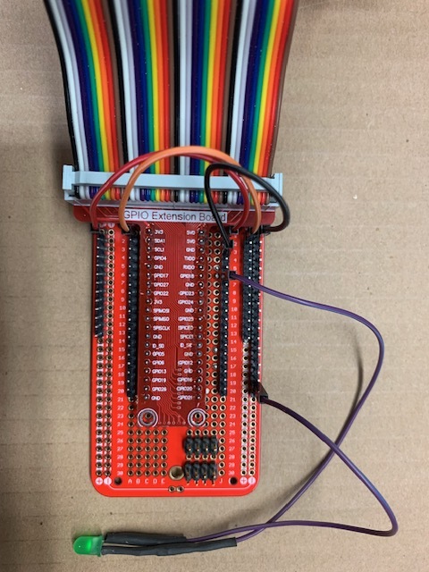
To calculate the resistor size, you can use this LED Series Resistor Calculator by DigiKey.
Run sample program
The example program can be called passing the parameter -a for the address, for example, in this configuration -a 2. But the program defaults to address 2. This means no parameter is required with this example when using dtoverlay=pwm.